top of page
914 '70-'74 Round Foglight Installation Instructions
LENS/BEZEL/LED BOARD ASSEMBLY
-
Remove the bumper by removing the four bolts, two on each side accessible from inside the wheel well.
-
Two people make the job much easier. As bolts are removed on the first side, have the helper hold the bumper steady while the other side bolts are removed. If no one is available, it is possible to use a 5 gallon bucket to rest the bumper on as the second side bolts are removed.
-
Remove the lens securing screw on the foglight fixture and remove the lens/bezel/reflector/bulb socket.
-
The power wire to the bulb socket is secured with a small screw. Loosen the screw and disconnect the socket.
-
Take the assembly to the workbench for disassembly.
-
SAFETY GLASSES MUST BE WORN FOR THE REMOVAL AND REPLACEMENT OF THE BEZEL SPRING CLIPS.
-
At the workbench, remove the four spring clips holding the assembly together.
-
Care must be taken to not lose the spring clips as they tend to launch themselves into the atmosphere at a high rate of speed.
-
Separate the lens, bezel, and reflector/bulb/socket. The reflector/bulb/socket will not be reused.
-
Clean/paint the bezel as desired at this point.
-
Examine the lens and replace if it appears sand-blasted from road debris.
-
Replace the lens gasket if not soft and supple or if it is ripped.
-
Install the gasket on the lens as shown. The gasket will sit inside the plastic ring on the LED board.
.jpg)
-
Insert the lens/gasket into the slot on the plastic ring starting with the notch on the lens. This is the top of the lens and assembly.
.jpg)
-
Insert the lens/gasket into the slot on the plastic ring starting with the notch on the lens. This is the top of the lens and assembly.
-
Work the lens/gasket all the way around the ring making sure the gasket sits squarely in the slot.
-
Care must be taken to make sure the gasket sits flush all the way around the slot like shown below.
.jpg)
-
If the gasket bulges at any place like shown below, readjust the lens/gasket until it is uniform all the way around. This is the seal between the lens and the bezel and must be uniform to keep moisture out.
.jpg)
-
A small clip insertion tool is provided with the kit.
-
You should have four spring clips for each foglight. If you don't have four for each, the clips can be purchased at 914rubber.com.
.jpg)
-
The LED board has four notches where the clips will hold the assembly.
-
DO NOT put the clips on the board itself as the clips may cause the board to bend and possibly affect the performance of the foglight.
.jpg)
-
Put the assembly in the bezel for final install.
-
The lens has a tiny notch on the bottom of the lens to align with a notch on the bezel. These two notches must be aligned for proper fit.
-
Work the clips back in place where the board notches are using the tool.
-
The assembly tends to squirm around while installing the clips and may need to be adjusted as each clip is installed. This is true especially when the first and second clips are installed.
.jpg)
.jpg)
.jpg)
.jpg)
-
The LED foglight assembly is ready to be installed on to the vehicle.
.jpg)
.jpg)
ASSEMBLY INSTALLATION:
-
Four crimp connectors are provided; only 2 are needed; 2 are extra in case anything goes wrong with the first set.
-
The crimp connectors are different:
-
The yellow connectors are for larger gauge wire and go on the driver side. The driver side of the 914 has 2 wires soldered together; one comes from the foglight relay in the cabin; the other wire goes over to the passenger side foglight.
-
The blue connectors are for the passenger side.
-
-
Crimp the yellow connector on the driver side and blue connector on the passenger side.
-
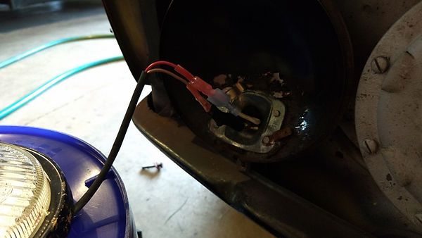
Remove the ground spade connector from the foglight fixture. Because the ground connector may be oxidized and quite difficult to remove like the one shown, DO NOT pull on the wire. Use a flat head screw driver and push the spade connector off of the ground tab on the fixture.
.jpg)
.jpg)
-
Place the lens/bezel/foglight assembly on a chair or bucket as shown and connect the wires:
-
The red wire connects to the power spade connector
-
The brown wire connects to the ground spade connector
-
-
Test the foglight to make sure it powers up ok.
.jpg)
.jpg)
-
Carefully install the lens/bezel/foglight assembly onto the rear of the fixture making sure the wires do not get pinched.
-
Replace the locking clip to hold the lens/bezel/foglight assembly on to the rear of the fixture.
-
Retest the foglight to make sure it works.
-
Because the LED foglight does not have a sharp upward light cutoff, it may be desirable to aim the foglight fixture 5 to 7.5 degrees downward.
.jpg)
bottom of page